 This documentation is released under the Creative Commons license
This module assigns IP addresses and sets up static routing for an IPv4 network. It assigns per-interface IP addresses, strives to take subnets into account, and can also optimize the generated routing tables by merging routing entries.
IMPORTANT: as of INET 2.2, this module does NOT assign addresses or add routes directly, just stores them in its internal data structures. Network nodes are supposed to contain an instance of IPv4NodeConfigurator (normally part of the network layer compound module) that actually configures the node's interface table and routing table based on the information stored in the global network configurator module.
The configurator supports both manual and automatic address assignment, and their combinations. You can provide address and netmask templates with unspecified parts, and the configurator automatically completes them by trying to put nodes on the same LAN into the same subnet. It also supports manual routes, and automatic routes that follow the shortest paths. By default, the configurator adds default routes where applicable (e.g. in hosts) and does subnet-based routing.
Hierarchical routing can be set up by using only a fraction of configuration entries compared to the number of nodes. The configurator also does routing table optimization that significantly decreases the size of routing tables in large networks.
Most of the above features can be turned on and off using NED parameters. The details (interface address and netmask templates, manual routes, etc.) can be configured in a single XML file for the whole network.
Modules that represent network nodes (host, hub, bus, switch, access point, router, etc.) are expected to have the @networkNode property, becaue that's how the configurator recognizes them in the model. All nodes must have their interface table (InterfaceTable module) as their "interfaceTable" submodule. All routers must have their routing table (IPv4RoutingTable module) as their "routingTable" or "networkLayer.routingTable" submodule.
By default all interfaces in all nodes will have a unique IPv4 address assigned. Routing tables will be configured so that there's a route following the shortest path from any node to any interface. In other words, all interfaces will be reachable from all nodes (e.g. ping).
The configurator doesn't connect to any other modules (it has no gates), and should have only one instance in the whole model. The configuration takes place in initialization stage 2 after the interfaces are registered in the InterfaceTable modules.
The configurator goes through the following configuration steps:
The following example configures all interfaces in the IPv4 address range 10.0.0.0 - 10.255.255.255, and netmask range 255.0.0.0 - 255.255.255.255. This is the default configuration.
<config>
  <interface hosts='**' address='10.x.x.x' netmask='255.x.x.x'/>
</config>
The following example configures a hierarchical network in a way that keeps routing tables small.
<config>
  <interface hosts="area11.lan1.*" address="10.11.1.x" netmask="255.255.255.x"/>
  <interface hosts="area11.lan2.*" address="10.11.2.x" netmask="255.255.255.x"/>
  <interface hosts="area12.lan1.*" address="10.12.1.x" netmask="255.255.255.x"/>
  <interface hosts="area12.lan2.*" address="10.12.2.x" netmask="255.255.255.x"/>
  <interface hosts="area*.router*" address="10.x.x.x" netmask="x.x.x.x"/>
  <interface hosts="*" address="10.x.x.x" netmask="255.x.x.0"/>
</config>
The XML configuration must contain exactly one <config> element. Under the root element there can be multiple of the following elements.
The following diagram shows usage relationships between types. Unresolved types are missing from the diagram.

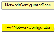
The following diagram shows inheritance relationships for this type. Unresolved types are missing from the diagram.
| Name | Type | Description |
|---|---|---|
| NetworkConfiguratorBase | simple module | (no description) |
| Name | Type | Description |
|---|---|---|
| advanced | network | (no description) |
| AggregationTest2 | network | (no description) |
| AODVNetwork | network | (no description) |
| ARPTest | network | (no description) |
| ARPTest | network | (no description) |
| Backbone | network | (no description) |
| ber | network | (no description) |
| BGPNet | network | (no description) |
| BGPTest | network | (no description) |
| BGPTest | network | (no description) |
| BGPTest | network | (no description) |
| BGPTest | network | (no description) |
| BGPTest | network | (no description) |
| BulkTransfer | network | (no description) |
| ClientServer | network | (no description) |
| ClientServerWithSM | network | (no description) |
| ClientServerWithSM | network | (no description) |
| CloudAndHosts | network | (no description) |
| CloudAndRouters | network | (no description) |
| ComplexConfiguratorNetwork | network | (no description) |
| Complexer | network | (no description) |
| ConfiguratorA | network | (no description) |
| ConfiguratorC | network | (no description) |
| ConfiguratorE | network | (no description) |
| ConfiguratorF | network | (no description) |
| Crosstalk | network | (no description) |
| DataLinkVisualizationExample | network | (no description) |
| DataLinkVisualizerEnablingWiredShowcase | network |
TODO documentation |
| DataLinkVisualizerEnablingWirelessShowcase | network |
TODO documentation |
| DataLinkVisualizerFilteringShowcase | network |
TODO documentation |
| DataLinkVisualizerMobileShowcase | network |
TODO documentation |
| DHCPShutdownReboot | network | (no description) |
| DiffservNetwork | network | (no description) |
| DiffservNetwork | network |
This network contains a router with an 10Mbps Ethernet interface, and with a 128kbps dialup connection to a server. |
| DYMONetwork | network |
TODO |
| DynamicNetworkRouteVisualizationExample | network | (no description) |
| DynamicRadioNetwork | network | (no description) |
| DynamicTest | network | (no description) |
| DynamicTest | network | (no description) |
| EarthCloud | network | (no description) |
| EarthVisualization3 | network | (no description) |
| ErrorRateExample | network | (no description) |
| ErrorRateTest | network | (no description) |
| FilteringShowcase | network | (no description) |
| FlatNet | network | (no description) |
| GPSRNetworkManual | network | (no description) |
| GPSRNetworkRandom | network |
TODO |
| HandoverNetwork | network | (no description) |
| HiddenNodeShowcase | network | (no description) |
| Hierarchical | network | (no description) |
| Http10Servers | network |
10-nodes test scenario for sockets. |
| HttpNnodes | network |
n-nodes test scenario for sockets. |
| HttpSockPair | network | (no description) |
| IconAppearanceShowcase | network |
TODO documentation |
| Ieee80211VisualizationAdvancedFeaturesShowcase | network | (no description) |
| Ieee80211VisualizationDisplayingAssociationsShowcase | network | (no description) |
| Ieee80211VisualizationExample | network | (no description) |
| Ieee80211VisualizationVisualizingHandoverShowcase | network | (no description) |
| InfoVisualizationExample | network | (no description) |
| InstrumentShowcase | network | (no description) |
| InterfaceTableVisualizationAdvancedFeaturesShowcase | network | (no description) |
| InterfaceTableVisualizationEnablingVisualizationShowcase | network | (no description) |
| InterfaceTableVisualizationExample | network | (no description) |
| Ipv4hook | network |
TODO Auto-generated network |
| IPv4LargeNet | network |
A large Ethernet LAN -- see model description |
| KIDSNw1 | network | (no description) |
| Lan80211 | network | (no description) |
| Layered80211 | network | (no description) |
| LayeredAPSK | network | (no description) |
| LevelofDetail | network | (no description) |
| LinkBreakA | network | (no description) |
| LinkBreakVisualizationExample | network | (no description) |
| MacTest | network | (no description) |
| MediumActivityDisplayingPropagationTransmissionsReceptionsShowcase | network | (no description) |
| MediumActivityInterferingSignalsShowcase | network | (no description) |
| MediumActivityMultipleNodesShowcase | network | (no description) |
| MixedNetwork | network |
TODO Auto-generated network |
| multi | network | (no description) |
| MulticastNetwork | network | (no description) |
| MultiRadio | network |
Models a network with several hosts. Each host may contain one or more radios. Nodes are using adhoc routing to pass information. |
| MultiRadio | network | (no description) |
| NClients | network | (no description) |
| NClients | network | (no description) |
| NClients | network | (no description) |
| NClients2 | network | (no description) |
| NeighborCacheTest | network | (no description) |
| Net | network | (no description) |
| Net | network | (no description) |
| Net80211 | network | (no description) |
| Network | network |
TODO documentation |
| Network | network | (no description) |
| Network | network |
A generated network with grid topology. |
| NetworkPathComplexShowcase | network |
TODO documentation |
| NetworkPathMobileShowcase | network |
TODO documentation |
| NetworkPathRIPShowcase | network |
TODO documentation |
| NetworkPathSimpleShowcase | network |
TODO documentation |
| ObjectCacheTest | network | (no description) |
| ObstacleIntersectionTest | network | (no description) |
| ObstacleLossVisualizationEnablingShowcase | network | (no description) |
| ObstacleLossVisualizationExample | network | (no description) |
| ObstacleLossVisualizationMultipleObstaclesShowcase | network | (no description) |
| ObstacleTest | network | (no description) |
| OSPF_AreaTest | network | (no description) |
| OSPF_BackboneAndOneStubTest | network | (no description) |
| OSPF_BackboneAndTwoStubsTest | network | (no description) |
| OSPF_BackboneTest | network | (no description) |
| OSPF_mininet | network | (no description) |
| OSPF_RFC2328_Fig6 | network | (no description) |
| PacketDropArpResolutionFailedShowcase | network | (no description) |
| PacketDropInterfaceNotConnectedShowcase | network | (no description) |
| PacketDropMacRetryLimitReachedShowcase | network | (no description) |
| PacketDropNoRouteToDestinationShowcase | network | (no description) |
| PacketDropQueueOverflowShowcase | network | (no description) |
| PacketDropVisualizationExample | network | (no description) |
| PcapRecorderTest | network | (no description) |
| PhysicalLinkVisualizationExample | network | (no description) |
| PhysicalLinkVisualizerEnablingShowcase | network |
TODO documentation |
| PhysicalLinkVisualizerFilteringShowcase | network |
TODO documentation |
| PhysicalLinkVisualizerMobileShowcase | network |
TODO documentation |
| PIM_SM_Network | network | (no description) |
| pimDMFinal | network | (no description) |
| PowerConsumptionShowcase | network | (no description) |
| PowerNetwork | network | (no description) |
| PropagationD | network | (no description) |
| PropagationE | network | (no description) |
| QosThroughput | network | (no description) |
| QosThroughput | network | (no description) |
| R37 | network | (no description) |
| RateControlExample | network | (no description) |
| RIPInfinityCountTest | network | (no description) |
| RouterPerfNetwork | network | (no description) |
| RoutingTableVisualizationDisplayingAllShowcase | network | (no description) |
| RoutingTableVisualizationDynamicShowcase | network | (no description) |
| RoutingTableVisualizationExample | network | (no description) |
| RoutingTableVisualizationFilteringShowcase | network | (no description) |
| RSVPTE4 | network |
Example network to demonstrate RSVP-TE. |
| RTPMulticast1 | network | (no description) |
| RTPNetwork | network | (no description) |
| RTPUnicast1 | network | (no description) |
| RTPUnicast2 | network | (no description) |
| ScalingExampleNetwork | network | (no description) |
| ShortestPath | network | (no description) |
| SignalPropagationVisualizationExample | network | (no description) |
| SimpleConfiguratorNetwork | network | (no description) |
| SimpleRREQ | network | (no description) |
| SimpleRREQ2 | network | (no description) |
| SimpleTest | network | (no description) |
| SimpleTest | network | (no description) |
| StaticNetworkRouteVisualizationExample | network | (no description) |
| StatisticVisualizationExample | network | (no description) |
| StatisticVisualizationPacketErrorRateShowcase | network | (no description) |
| StatisticVisualizationPingRttShowcase | network | (no description) |
| StylingShowcase | network |
TODO documentation |
| SubmoduleInformationVisualizationShowcase | network | (no description) |
| Synchronized | network | (no description) |
| tcpsack | network | (no description) |
| tcptimestamps | network | (no description) |
| tcpwindowscale | network | (no description) |
| testNetwork | network | (no description) |
| TestNic | network | (no description) |
| TestRadioScaling | network | (no description) |
| Throughput | network | (no description) |
| TransportConnectionVisualizationEnablingShowcase | network | (no description) |
| TransportConnectionVisualizationExample | network | (no description) |
| TransportConnectionVisualizationMultipleConnectionsShowcase | network | (no description) |
| TransportPathVisualizerExtendedShowcase | network |
TODO documentation |
| TransportPathVisualizerServerClientsShowcase | network |
TODO documentation |
| TransportPathVisualizerSimpleWiredShowcase | network |
TODO documentation |
| TransportPathVisualizerSimpleWirelessShowcase | network |
TODO documentation |
| TransportRouteVisualizationExample | network | (no description) |
| UDPBroadcastNetwork | network | (no description) |
| UDPBurst | network | (no description) |
| VisualizationD | network | (no description) |
| VisualizationTutorialA | network | (no description) |
| Voip | network |
A generated network with star topology. |
| WiredAndWirelessHostsWithAP | network | (no description) |
| WiredNetWithDHCP | network | (no description) |
| WirelessA | network | (no description) |
| WirelessNetWith2DHCP | network | (no description) |
| WirelessNetWithDHCP | network | (no description) |
| Name | Type | Default value | Description |
|---|---|---|---|
| minLinkWeight | double | 1E-3 | |
| config | xml | xml(" |
XML configuration parameters for IP address assignment and adding manual routes |
| assignAddresses | bool | true |
assign IP addresses to all interfaces in the network |
| assignDisjunctSubnetAddresses | bool | true |
avoid using the same address prefix and netmask on different links when assigning IP addresses to interfaces |
| addStaticRoutes | bool | true |
add static routes to the routing tables of all nodes to route to all destination interfaces (only where applicable; turn off when config file contains manual routes) |
| addDefaultRoutes | bool | true |
add default routes if all routes from a source node go through the same gateway (used only if addStaticRoutes is true) |
| addSubnetRoutes | bool | true |
add subnet routes instead of destination interface routes (only where applicable; used only if addStaticRoutes is true) |
| optimizeRoutes | bool | true |
optimize routing tables by merging routes, the resulting routing table might route more packets than the original (used only if addStaticRoutes is true) |
| dumpTopology | bool | false |
print extracted network topology to the module output |
| dumpLinks | bool | false |
print recognized network links to the module output |
| dumpAddresses | bool | false |
print assigned IP addresses for all interfaces to the module output |
| dumpRoutes | bool | false |
print configured and optimized routing tables for all nodes to the module output |
| dumpConfig | string | "" |
write configuration into the given config file that can be fed back to speed up subsequent runs (network configurations) |
| Name | Value | Description |
|---|---|---|
| class | IPv4NetworkConfigurator | |
| display | i=block/cogwheel_s |
//
// This module assigns IP addresses and sets up static routing for an IPv4 network.
// It assigns per-interface IP addresses, strives to take subnets into account,
// and can also optimize the generated routing tables by merging routing entries.
//
// IMPORTANT: as of INET 2.2, this module does NOT assign addresses or add
// routes directly, just stores them in its internal data structures.
// Network nodes are supposed to contain an instance of ~IPv4NodeConfigurator
// (normally part of the network layer compound module) that actually
// configures the node's interface table and routing table based on the
// information stored in the global network configurator module.
//
// The configurator supports both manual and automatic address assignment,
// and their combinations. You can provide address and netmask templates
// with unspecified parts, and the configurator automatically completes
// them by trying to put nodes on the same LAN into the same subnet.
// It also supports manual routes, and automatic routes that follow the
// shortest paths. By default, the configurator adds default routes where
// applicable (e.g. in hosts) and does subnet-based routing.
//
// Hierarchical routing can be set up by using only a fraction of configuration
// entries compared to the number of nodes. The configurator also does
// routing table optimization that significantly decreases the size of routing
// tables in large networks.
//
// Most of the above features can be turned on and off using NED parameters.
// The details (interface address and netmask templates, manual routes, etc.)
// can be configured in a single XML file for the whole network.
//
// Modules that represent network nodes (host, hub, bus, switch, access point,
// router, etc.) are expected to have the @networkNode property, becaue that's how the
// configurator recognizes them in the model. All nodes must have their
// interface table (~InterfaceTable module) as their "interfaceTable" submodule.
// All routers must have their routing table (~IPv4RoutingTable module) as their
// "routingTable" or "networkLayer.routingTable" submodule.
//
// By default all interfaces in all nodes will have a unique IPv4 address
// assigned. Routing tables will be configured so that there's a route
// following the shortest path from any node to any interface. In other words,
// all interfaces will be reachable from all nodes (e.g. ping).
//
// The configurator doesn't connect to any other modules (it has no gates),
// and should have only one instance in the whole model.  The configuration
// takes place in initialization stage 2 after the interfaces are registered
// in the ~InterfaceTable modules.
//
// The configurator goes through the following configuration steps:
//
//  -# Builds a graph representing the network topology. The graph
//     will have a vertex for every module that has a @networkNode property (this
//     includes hosts, routers, and L2 devices like switches, access points,
//     Ethernet hubs, etc.) It also assigns weights to vertices and edges that
//     will be used by the shortest path algorithm when setting up routes.
//     Weights will be infinite for IP nodes that have IP forwarding disabled
///    (to prevent routes from transiting them), and zero for all other nodes
//     (routers and and L2 devices). Edge weights are chosen to be inversely
//     proportional to the bitrate of the link, so that the configurator
//     prefers connections with higher bandwidth. For internal purposes,
//     the configurator also builds a table of all "links" (the link data
//     structure consists of the set of network interfaces that are
//     on the same point-to-point link or LAN)
//
//  -# Assigns IP addresses to all interfaces of all nodes. The
//     assignment process takes into consideration the addresses and netmasks
//     already present on the interfaces (possibly set in earlier initialize
//     stages), and the configuration provided in the XML format (described
//     below). The configuration can specify "templates" for the address
//     and netmask, with parts that are fixed and parts that can be chosen
//     by the configurator (e.g. "10.0.x.x"). In the most general case,
//     the configurator is allowed to choose any address and netmask for all
//     interfaces (which results in automatic address assignment). In the most
//     constrained case, the configurator is forced to use the requested addresses
//     and netmasks for all interfaces (which translates to manual address assignment).
//     There are many possible configuration options between these two extremums. The
//     configurator assigns addresses in a way that maximizes the number of
//     nodes per subnet. Once it figures out the nodes that belong to a single
//     subnet it, will optimize for allocating the longest possible netmask.
//     The configurator might fail to assign netmasks and addresses according
//     to the given configuration parameters; if that happens, the assignment
//     process stops and an error is signalled.
//
//  -# Adds the manual routes that are specified in the configuration.
//
//  -# Adds static routes to all routing tables in the network. The
//     configurator uses Dijkstra's weighted shortest path algorithm to find
//     the desired routes between all possible node pairs. The resulting
//     routing tables will have one entry for all destination interfaces in the
//     network. The configurator can be safely instructed to add default routes
//     where applicable, significantly reducing the size of the host routing
//     tables. It can also add subnet routes instead of interface routes further
//     reducing the size of routing tables. Turning on this option requires
//     careful design to avoid having IP addresses from the same subnet on
//     different links. CAVEAT: Using manual routes and static route generation
//     together may have unwanted side effects, because route generation ignores
//     manual routes.
//
//  -# Then it optimizes the routing tables for size. This optimization allows
//     configuring larger networks with smaller memory footprint and makes the
//     routing table lookup faster. The resulting routing table might be
//     different in that it will route packets that the original routing table
//     did not. Nevertheless the following invariant holds: any packet routed
//     by the original routing table (has matching route) will still be routed
//     the same way by the optimized routing table.
//
//  -# Finally it dumps the requested results of the configuration. It can
//     dump network topology, assigned IP addresses, routing tables and its
//     own configuration format.
//
// The following example configures all interfaces in the IPv4 address range
// 10.0.0.0 - 10.255.255.255, and netmask range 255.0.0.0 - 255.255.255.255.
// This is the default configuration.
//
// <pre>
// <config>
//   <interface hosts='**' address='10.x.x.x' netmask='255.x.x.x'/>
// </config>
// </pre>
//
// The following example configures a hierarchical network in a way that keeps
// routing tables small.
// <pre>
// <config>
//   <interface hosts="area11.lan1.*" address="10.11.1.x" netmask="255.255.255.x"/>
//   <interface hosts="area11.lan2.*" address="10.11.2.x" netmask="255.255.255.x"/>
//   <interface hosts="area12.lan1.*" address="10.12.1.x" netmask="255.255.255.x"/>
//   <interface hosts="area12.lan2.*" address="10.12.2.x" netmask="255.255.255.x"/>
//   <interface hosts="area*.router*" address="10.x.x.x" netmask="x.x.x.x"/>
//   <interface hosts="*" address="10.x.x.x" netmask="255.x.x.0"/>
// </config>
// </pre>
//
// The XML configuration must contain exactly one <config> element. Under the
// root element there can be multiple of the following elements.
//
//  - <interface>
//    The interface element provides configuration parameters for one or more
//    interfaces in the network. The selector attributes limit the scope where
//    the interface element has effects. The parameter attributes limit the
//    range of assignable addresses and netmasks.
//
//    - @hosts
//      Optional selector attribute that specifies a list of host name patterns.
//      Only interfaces in the specified hosts are affected. The pattern might
//      be a full path starting from the network, or a module name anywhere in
//      the hierarchy, and other patterns similar to ini file keys. The default
//      value is "*" that matches all hosts.
//      e.g. "subnet.client*" or "host* router[0..3]" or "area*.*.host[0]"
//
//    - @names
//      Optional selector attribute that specifies a list of interface name
//      patterns. Only interfaces with the specified names are affected. The
//      default value is "*" that matches all interfaces.
//      e.g. "eth* ppp0" or "*"
//
//    - @towards
//      Optional selector attribute that specifies a list of host name patterns.
//      Only interfaces connected towards the specified hosts are affected. The
//      specified name will be matched against the names of hosts that are on
//      the same LAN with the one that is being configured. This works even if
//      there's a switch between the configured host and the one specified here.
//      For wired networks it might be easier to specify this parameter instead
//      of specifying the interface names. The default value is "*".
//      e.g. "ap" or "server" or "client*"
//
//    - @among
//      Optional selector attribute that specifies a list of host name patterns.
//      Only interfaces in the specified hosts connected towards the specified
//      hosts are affected.
//      The 'among="X Y Z"' is same as 'hosts="X Y Z" towards="X Y Z"'.
//
//    - @address
//      Optional parameter attribute that limits the range of assignable
//      addresses. Wildcards are allowed with using 'x' as part of the address
//      in place of a byte. Unspecified parts will be filled automatically be
//      the configurator. The default value "" means that the address will not
//      be configured. Unconfigured interfaces still have allocated addresses
//      in their subnets allowing them to become configured later very easily.
//      e.g. "192.168.1.1" or "10.0.x.x"
//
//    - @netmask
//      Optional parameter attribute that limits the range of assignable
//      netmasks. Wildcards are allowed with using 'x' as part of the netmask
//      in place of a byte. Unspecified parts will be filled automatically be
//      the configurator. The default value "" means that any netmask can be
//      configured.
//      e.g. "255.255.255.0" or "255.255.x.x" or "255.255.x.0"
//
//    - @mtu                number
//      Optional parameter attribute to set the MTU parameter in the interface.
//      When unspecified the interface parameter is left unchanged.
//
//    - @metric                number
//      Optional parameter attribute to set the Metric parameter in the interface.
//      When unspecified the interface parameter is left unchanged.
//
//    - @groups
//      Optional parameter attribute; it may contain a list of (multicast)
//      IP addresses that will be added to the multicast groups of the interface.
//      See also the <multicast-group> element.
//
//    - @add-static-route
//      Optional bool parameter (default=true).
//      Add static route to the routing table.
//
//    - @add-default-route
//      Optional bool parameter (default=true).
//      Add default route to the routing table if the node has only one non-loopback interface.
//
//    - @add-subnet-route
//      Optional bool parameter (default=true).
//      Add subnet route to the routing table.
//
//  - <wireless>
//    The wireless element specifies the members of a wireless network. It is
//    primarily useful when the members cannot be automatically determined using
//    the SSID parameters.
//
//    - @id (optional)
//      identifies wireless network, unique value used if missed
//
//    - @hosts
//      Optional selector attribute that specifies a list of host name patterns.
//      Only interfaces in the specified hosts are affected. The default value
//      is "*" that matches all hosts.
//
//    - @interfaces
//      Optional selector attribute that specifies a list of interface name
//      patterns. Only interfaces with the specified names are affected. The
//      default value is "*" that matches all interfaces.
//
//  - <multicast-group>
//    The multicast group element provides multicast network addresses for one
//    or more interfaces in the network.
//
//    - @hosts
//      Optional selector attribute that specifies a list of host name patterns.
//      Only interfaces in the specified hosts are affected. The default value
//      is "*" that matches all hosts.
//
//    - @interfaces
//      Optional selector attribute that specifies a list of interface name
//      patterns. Only interfaces with the specified names are affected. The
//      default value is "*" that matches all interfaces.
//
//    - @towards
//      Optional selector attribute that specifies a list of host name patterns.
//      Only interfaces connected towards the specified hosts are affected.
//      The default value is "*".
//
//    - @among
//      Optional selector attribute that specifies a list of host name patterns.
//      Only interfaces in the specified hosts connected towards the specified
//      hosts are affected.
//      The 'among="X Y Z"' is same as 'hosts="X Y Z" towards="X Y Z"'.
//
//    - @address
//      Mandatory parameter attribute that specifies a list of multicast group
//      addresses to be assigned. Values must be selected from the valid range
//      of multicast addresses.
//      e.g. "224.0.0.1 224.0.1.33"
//
//  - <route>
//    The route element provides routing table entries for multiple nodes
//    in the network. The selector attributes limit the scope where the route
//    element has effects.
//
//    - @hosts
//      Optional selector attribute that specifies a list of host name patterns.
//      Only routing tables in the specified hosts are affected. The default
//      value "" means all hosts will be affected.
//      e.g. "host* router[0..3]"
//
//    - @destination
//      Optional parameter attribute that specifies the destination address in
//      the route (L3AddressResolver syntax). The default value is "*".
//      e.g. "192.168.1.1" or "subnet.client[3]" or "subnet.server(ipv4)" or "*"
//
//    - @netmask
//      Optional parameter attribute that specifies the netmask in the route.
//      The default value is "*".
//      e.g. "255.255.255.0" or "/29" or "*"
//
//    - @gateway
//      Optional parameter attribute that specifies the gateway (next-hop)
//      address in the route (L3AddressResolver syntax). When unspecified
//      the interface parameter must be specified. The default value is "*".
//      e.g. "192.168.1.254" or "subnet.router" or "*"
//
//    - @interface
//      Optional parameter attribute that specifies the output interface name
//      in the route. When unspecified the gateway parameter must be specified.
//      This parameter has no default value.
//      e.g. "eth0"
//
//    - @metric
//      Optional parameter attribute that specifies the metric in the route.
//      The default value is 0.
//
//  - <multicast-route>
//    The multicast-route elements add entries to multicast routing tables.
//
//    - @hosts
//      Optional selector attribute that specifies a list of host name patterns.
//      Only routing tables in the specified hosts are affected.
//      e.g. "host* router[0..3]"
//
//    - @source
//      Optional parameter attribute that specifies the address of the source
//      network. The default value is "*" that matches all sources.
//
//    - @netmask
//      Optional parameter attribute that specifies the netmask of the source
//      network. The default value is "*" that matches all sources.
//
//    - @groups
//      Optional List of IPv4 multicast addresses specifying the groups this entry
//      applies to. The default value is "*" that matches all multicast groups.
//      e.g. "225.0.0.1 225.0.1.2".
//
//    - @metric
//      Optional parameter attribute that specifies the metric in the route.
//
//    - @parent
//      Optional parameter attribute that specifies the name of the interface
//      the multicast datagrams are expected to arrive. When a datagram arrives
//      on the parent interface, it will be forwarded towards the child interfaces;
//      otherwise it will be dropped. The default value is the interface on the
//      shortest path towards the source of the datagram.
//
//    - @children
//      Mandatory parameter attribute that specifies a list of interface name
//      patterns:
//       - a name pattern (e.g. "ppp*") matches the name of the interface
//       - a 'towards' pattern (starting with ">", e.g. ">router*") matches the interface
//         by naming one of the neighbour nodes on its link.
//      Incoming multicast datagrams are forwarded to each child interface except the
//      one they arrived in.
//
//  - <autoroute>
//    The autoroute element specifies parameters for the automatic static routing.
//    If this element is not specified then the configurator assumes a default.
//    The default specifies that all routing tables will be modified and all the
//    shortest path to all interfaces will be computed.
//
//    - @sourceHosts
//      Optional selector attribute that specifies a list of host full path patterns.
//      It determines the set of routing tables that will be modified. The default
//      value is "**".
//
//    - @destinationInterfaces
//      Optional parameter attribute that specifies a list of interface full path
//      patterns. It determines the set of destination interfaces for which the
//      shortest path will be computed. The default value is "**".
//
//    - @metric
//      Optional parameter attribute that determines the metric that is used to
//      compute the shortest paths. Valid values are: "hopCount", "delay", "dataRate",
//      and "errorRate". The default value is "hopCount".
//
//    - <node>
//      The node optional subelement specifies cost parameters for the shortest
//      path algorithm. If this subelement is not specified then the configurator
//      determines cost by default according to the selected metric.
//
//      - @hosts
//        Mandatory selector attribute that specifies a list of node full path
//        patterns. It determines the affected set of nodes.
//
//      - @cost
//        Mandatory parameter attribute that specifies the cost. Valid values are
//        "infinite" and numbers.
//
//    - <link>
//      The node subelement specifies cost parameters for the shortest path algorithm.
//      If this subelement is not specified then the configurator determines link
//      cost by default according to the selected metric.
//
//      - @interfaces
//        Mandatory selector attribute that specifies a list of interface full
//        path patterns. It determines the affected set of links connected to
//        the given interfaces.
//
//      - @cost
//        Mandatory parameter attribute that specifies the cost. Valid values are
//        "infinite" and numbers.
//
simple IPv4NetworkConfigurator extends NetworkConfiguratorBase
{
    parameters:
        @class(IPv4NetworkConfigurator);
        @display("i=block/cogwheel_s");
        xml config = default(xml("<config><interface hosts='**' address='10.x.x.x' netmask='255.x.x.x'/></config>")); // XML configuration parameters for IP address assignment and adding manual routes
        bool assignAddresses = default(true); // assign IP addresses to all interfaces in the network
        bool assignDisjunctSubnetAddresses = default(true); // avoid using the same address prefix and netmask on different links when assigning IP addresses to interfaces
        bool addStaticRoutes = default(true);  // add static routes to the routing tables of all nodes to route to all destination interfaces (only where applicable; turn off when config file contains manual routes)
        bool addDefaultRoutes = default(true); // add default routes if all routes from a source node go through the same gateway (used only if addStaticRoutes is true)
        bool addSubnetRoutes = default(true);  // add subnet routes instead of destination interface routes (only where applicable; used only if addStaticRoutes is true)
        bool optimizeRoutes = default(true); // optimize routing tables by merging routes, the resulting routing table might route more packets than the original (used only if addStaticRoutes is true)
        bool dumpTopology = default(false);  // print extracted network topology to the module output
        bool dumpLinks = default(false);     // print recognized network links to the module output
        bool dumpAddresses = default(false); // print assigned IP addresses for all interfaces to the module output
        bool dumpRoutes = default(false);    // print configured and optimized routing tables for all nodes to the module output
        string dumpConfig = default("");     // write configuration into the given config file that can be fed back to speed up subsequent runs (network configurations)
}
This documentation is released under the Creative Commons license